| This is my second
venture into the esoteric world of airfoil section design.
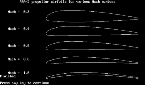
The first effort was based on the ARA-D family of airfoils,
which were developed for operation on propellers running high
tip speeds: that is to say, at Mach numbers approaching unity.
At the propeller tips, these airfoils approach very thin positively-
cambered flat plates (see supercoolprops.com, click on articles,
click on “Transonic airfoils for propellers”).
I found that the application of these sections was hindered
by my having no real data for them: in particular, the zero-lift
angle was unknown. My efforts to find the zero-lift angle
using X-foil came to nought, as I couldn’t get X-foil
to run. Even if it had, I’m not at all sure that X-foil
would handle the transonic tip regime, which, in some applications,
such as F2A and F3D, is the defining problem. Some codes attempt
to handle compressibility using the Glauert-Prandtl rule,
which is OK for free-stream velocities up to about Mach 0.7,
but which breaks down as soon as local velocities over the
airfoil exceed Mach 1: ie, when shock waves form. (Actually,
X-foil uses a modified/improved version of Glauert-Prandtl).
I have been pondering the transonic airfoil problem now
for about 20 years, during which time the fog of ignorance
has lifted little by little, as indeed the fog lifted briefly
for the Indian asylum inmate, Chief Bromden, in Ken Kesey’s
“One flew over the Cuckoos Nest” (Picador Edition,
1973). Been there, done that, so now you know where I’m
coming from!
The fog has lifted sufficiently now for me to offer this
contribution to the Glory of Supercool. However, it is not
a pretty sight. For this reason, I have designated my “new”
airfoils as belonging to an “egregious” caste
of design. The word “egregious” has a number of
quite charming definitions, which I should share with you
now. The Concise Oxford dictionary offers “outstandingly
bad”, and “standing out from the flock”.
The Readers Digest Reverse Dictionary offers “outrageously
and glaringly bad”. Websters offers “flagrant:
outstanding in bad or evil qualities”; curiously, it
also offers a Latin derivation, ex-grex, meaning “out
of the herd”. You choose.
OK, you are trapped now. You cannot accuse me of being crazy,
because I’ve already admitted that. And if I am right,
in the parallel universe which aeronautical engineers inhabit,
then the same principle, which governs the naming of comets,
applies to my appropriation of the word “egregious”
to my “new airfoils”. This term is a bit wordy.
So I shall adopt the abbreviation “eggfoils”,
in obvious notation, for the remainder of this text.
Now let us progress this issue a little. The ante-bellum situation
of transonic airfoil theory to my mind indicates a fixation
with positive camber. Whenever airfoil mods are made, there
is a desperate attempt to get positive camber somewhere in
the airfoils, if not at the leading edge, then at the trailing
edge: such as these are the Whitcomb “supercritical”
sections. The theory behind them is some confusing summation
of shock waves over the blunt leading edge, with a desperate
attempt to get some lift by “rear-loading” at
the trailing edge. Designations such as “roof-top”
sections amuse me, being consistent with my own “eggfoil”
language.
The key parameters in these airfoil developments are compressibility
and shock-wave formation. I should indicate the meaning of
these terms briefly, although they are well covered elsewhere.
“compressibility” refers to the fact that the
air cannot get out of the way quickly enough from an approaching
airfoil. As a result, the air molecules can come closer together,
increasing their pressure and density: in other words, compressing
the air in the vicinity of the airfoil: particularly, at the
“stagnation point” of the leading edge, where
the airflow separates to go both over and under the airfoil.
“Shock waves”, on the other hand, are a rather
exotic phenomenon, outside our normal experience. Passing
over the airfoil at transonic speeds (0.7 < M < 1),
there is a region where the local flow velocity exceeds the
speed of sound. I have seen these referred to as “bubble
regions”, which is poor terminology, as the same words
are used for flow behaviour at low Reynolds and low Mach numbers
at the points where flow separation and re-attachment occur
on an airfoil upper surface.
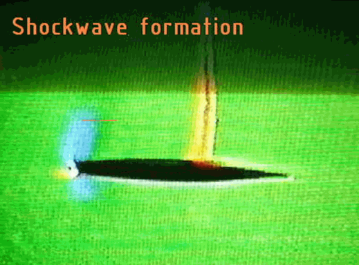
(In the illustration above, at the leading edge, “yellow”
is high pressure air, while blue is low pressure air ).
This aside, when the local airflow velocity falls below Mach
unity, a sharply defined transition line appears. Ahead of
this line, the airflow is smooth and supersonic: behind it,
the airflow the total pressure and velocity have fallen while
the temperature has increased (ref. 1, p17). These characteristics
extend away from the airfoil surface into the free-stream.
This transition surface is called a “shock wave”.
The transition from supersonic to subsonic flow is very defined,
being of sub-millimetre thickness.
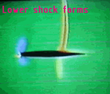
The main effect of the shock is to increase drag; this source
of drag being designated “wave drag”. The stronger
the shock, the greater the drag. In other words, the principal
component of airfoil drag in the transonic region is wave
drag (the energy going into heat aft of the shock).
However, reading various texts, one is lead to believe that
the shock wave is also responsible for either a loss in lift
coefficient and/or an increase in downward pitching moment.
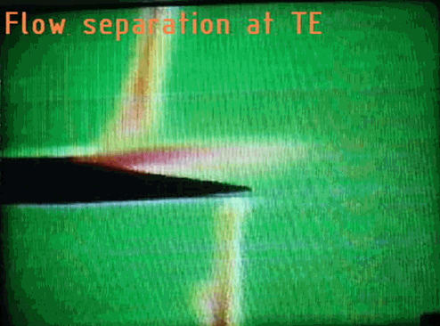
The standard reason given for this loss of lift is that flow
separation takes place behind the shock: this shock-stall
is analogous to the subsonic process involved in stalling
a wing. Hmm, why am I not convinced of that? Abbott and Von
Doenhoff (ref. 2, p269) are delightfully vague on this. “Compressibilty”
gets the blame.
OK. So I’m a heretic. Fancy having the nerve to criticise
the Bible of aerodynamics (ref. 2). The truth is this: I am
shifting the goal posts. Propellers do not have to land at
the end of a flight: wings do. I am looking at airfoil data
from the viewpoint of propellers: not wings.
Well, while I’m being hung out to dry, let’s
go all the way. Apart from the delightful Max Munk and the
insightful R.T.Jones, the engineers at the old NACA were renowned
for their inability to see the obvious. With the clear vision
provided by 50 years of hindsight (by the way, I am 65 years
old), it is apparent to me that NACA missed the boat back
in 1949. It was close to 1970 before airfoils capable of being
operated satisfactorily at transonic speeds became available,
yet it is my thesis that they had already had transonic data
in 1949 that could be applied to propellers, if not wings,
already in their domain.
How can I, an antipodean with no formal aerodynamic education,
completely outside the mainstream (read “herd”),
make such an assertion? Well lets look again at ref 2, Abbott
and Von Doenhoff’s masterpiece, which I must now abbreviate
to AVD. Page 276 Figure 165 shows the effect of Mach number
on lift coefficient for various angle of attack for the NACA
2315 airfoil. Above M = .6, the lift coefficient falls rapidly
as Mach number rises from .6 to .85. Above .85, it rises again.
Now look at p268, Figure 155. For NACA 23015, the pitching
moment becomes more negative above M = 0.6, falling from zero
to –0.05 at M = .77.
My question is, why? Do AVD explain the shape of these curves?
No.
AVD is full of really great data on the transonic performance
of airfoils: but do they interpret these data in a way that
would make the data useful to us propeller designers? No.
One looks at their data, and thinks: by golly, about all I
can do for my propellers is to make them thin and symmetrical
at the tips and hope to hell that they do some work in the
transonic region, rather than just producing lots of drag
for very little lift. I mean to say, if one were to assume
that the 2 dimensional data in, for example, Figure 164, for
NACA 2312, applied, then my tip airfoils could easily be making
negative thrust! Not good. Negative efficiency. What would
Fred Weick (ref. 3) have to say about that?
OK. Its time to put up or shut up. Well, not quite yet. We
are still ante-bellum.
Now is the time to explain the lift coefficient curves found
in AVD. To achieve this, we need a little extra information.
For this, I defer to Bill Gunston’s wonderful coffee-table
book, “Faster than Sound”, (ref. 4). This book
should be in every Doctors and Dentists waiting room. I rarely
pay full price for any book, preferring to scavenge through
remaindered items hoping to find a Pearl. But I paid full
price for this one. Apart from a small error in propeller
theory, top of page 76, this book is quite remarkable for
the insights it gives into supersonic flow.
The insight I now wish to present will either hang me or
put me up there on a pedestal with Lincoln. If I read Gunston
aright, we have two flow regimes, which are completely opposite
in character.
Subsonic expansive flow over an airfoil surface produces
a DECREASE in pressure over the airfoil surface.
Supersonic compressive flow over an airfoil surface produces
an INCREASE in pressure over the airfoil surface.
That’s it. The lift vector reverses between subsonic
and supersonic flow regimes. If this is true, then AVD’s
lift curves can be explained in simple terms.
We’ll take an example. AVD, p275, figure 163, NACA
2309 at 2 degrees angle of attack. Consider the airfoil upper
surface, remembering that the camber of this airfoil is positive.

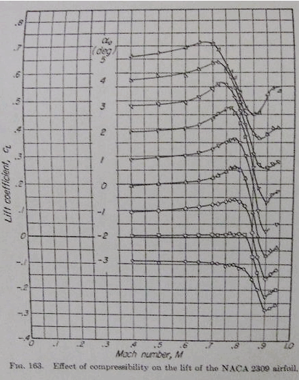
From M = 0 to M = 0.77, the lift coefficient Cl rises nicely
according to the Glauert-Prandtl rule. Flow is totally subsonic;
there are no shock waves. Peace on Earth, goodwill to propellers.
From M = 0.77 to M = 0.9, Cl falls from 0.47 to 0.13. At
M = 0.77, the local airflow over the airfoil is just touching
Mach 1 at some point, near the airfoil high-point. A shock
is appearing just downstream of this point. At a bit higher
Mach number, the extent of the supersonic region has increased.
The lift vector has reversed in the supersonic region, and
Cl is forcibly reduced. The shock wave is strengthening, adding
to the drag.
At M = 0.9, the supersonic region has progressed to cover
the major part of the surface. With the lift vector reversed
over the supersonic region and flow separation behind the
shock, Cl is drastically reduced over this part of the surface.
Somewhere behind the surface high-point, the shock wave is
strong, with the flow downstream of the shock slowed to below
Mach 1.
In summary, the reduction in Cl has been due to increase
in pressure due to supersonic flow and also to flow-separation.
Now consider the lower surface. As this airfoil we are considering
has positive camber, the lower surface has less curvature.
Supersonic flow occurs at a higher Mach number than for the
upper surface, which means the lower surface shock is also
delayed to the higher Mach number. The flow near the leading
edge is less than Mach one, so it is compressive/subsonic
and the lift vector remains downward, adding to the reversed
lift vector. The nett effect is to lower the lift coefficient.
This completes phase one of this dissertation. We must now
move on to the post-bellum arguments, which will allow us
to describe the eggfoils suitable for use on propellers in
the difficult transonic region.
So how do we get an airfoil suitable for, say, M = 0.9 ?
No problem. Turn to AVD p275, figure 163. This is NACA 2309,
with 2% positive camber, camber-line high point at 30% and
9% t/c. At mach .9 and 2 degrees angle of attack, we have
Cl = 0.13. From figure 177, the drag coefficient Cd = 0.058.
Thus for NACA2309, Cl / Cd = 2.24.
Now turn the book through 180 degrees so that figure 163
is upside down. Don’t laugh, this is really getting
serious about literature.
This is the data for your new airfoil, EGGFOIL –2309.
It is the same as NACA2309, but has negative camber of 2%:
ie, it is now upside down. We can read the data off, just
as before. For 2 degrees angle of attack, Cl = 0.23 and from
figure 177 again, Cd = 0.053.
Then for EGGFOIL –2309, Cl / Cd = 4.4.
Lets not kid ourselves, these are lousy L/D’s, but
the fact is that the EGGFOIL –2309 is better than NACA
2309 by a factor of 4.4 / 2.24 = 1.7. That’s better
than a kick in the head! But it gets better!
Let’s try the same exercise for one degree angle of
attack. Then Cl / Cd for positive camber is .025 / .051 =
0.49 while for negative camber we have 0.16 / 0.048 = 3.3,
an improvement factor of 6.8 !
Thus, turning 2309 upside down greatly improves its performance
at Mach 0.9. In view of the ante-bellum discussion above,
it should be clear why. In turning the airfoil upside down,
we have reduced the supersonic flow component on the upper
surface, hence reducing the strength of the shock wave. We
still get lift on the lower surface, as due to circulation
its velocity is less then Mach 1 (except possibly for a small
region back from the Leading edge). Then subsonic expansion
behind the high point yields undersurface pressure which is
in fact a component of lift. Win win!
The practical ramifications of this airfoil choice are probably
the following.
In racing models, we are using airfoil chords as low as 7mm.
With a 9% t/c, aero-elastic problems with the carbon fibre
props are becoming significant. For my wet moulding techniques,
I cannot really go lower than 9% and still have a tip with
known geometry.
Then there is the question of flow pressures at the tips.
AVD on p296 refer to the phenomenon of “tip relief”.
You can read that for yourself, but the notion is that 2-dimensional
flow data do not apply to the 3-dimensional flow found at
propeller tips. Thus Mach 0.9 for 2D flow is more likely equivalent
to 3D flow at Mach 0.8. We are not out the woods, for both
F2A and F3D tip speeds are in excess of M = 0.95 already.
There are two real gains that we have made. At least we know
the zero-lift angle for the eggfoils: secondly, we have a
baseline for developing better eggfoils, which can be tested
systematically by flight tests. Maybe we can do better in
the dreaded critical Mach number zone after all!
In case you have forgotten where we were going: the idea
is to use negative camber airfoils (eggfoils) for propellers
operating in the transonic region.
Coming soon to an asylum near you: “Transonic airfoils
Part 2: Dance of the Shock Waves by Joe Supercool”
Watch for it, the test flying has already been done!
References:
1. Design for Air Combat. Ray Whitford. Jane’s Publishing
Company Ltd., 1987. ISBN 0 7106 0426 2
2. Theory of Wing Sections. Abbott and Von Doenhoff. Dover,
1949. Standard Book Number 486-60586-8
3. Aircraft Propeller Design. Fred Weick. McGraw-Hill Book
Company. 1930
4. Faster than Sound. The story of supersonic flight. Bill
Gunston. Patrick Stevens Limited. ISBN 1 85260 317 8
|