| OK, here we are
back in the Fluid Dynamics topic. But this time we will do
something useful. Yup, we will apply it to a central problem in
propeller design. And about time too! We will have a look at how
the rubbish trailing along behind the propeller (like engine,
wing, fuselage, pilot etc) affects the design of the propeller.
The key design parameters for propellers are diameter,
RPM,engine power and airspeed into the prop disc. You might
think this latter quantity, the velocity of flow into the prop
disc,is just the airspeed. Well, it is and it isn’t. You see,the
prop is really only interested in the axial component of
airspeed, not the flow pushed out radially by the cowl and
fuselage. It turns out that this axial component is slower than
the airspeed, which means that we need less pitch than we might
otherwise have thought. In fact, it can be quite a lot less if
we have a big fat radial engine getting in the way.
So now we will find a way to calculate the axial flow as a
function of the distance out along the prop.
Fluid Dynamics provides a method to follow. Here is the bit
I like. The method is so good that we don’t need to do
measurements to validate the calculations! Now that is a big
claim! But unless you can think of some way to measure the flow
field around an engine cowl, we might as well go with it. My
attention was drawn to this method by E.R.Jones.Here is what he
said. “The calculation is approximate, but is sufficiently
accurate for its intended use..it has the added advantage of
visualising the flow around the nose of the aircraft, and
therefore permits a better understanding ofjust what is
happening there.” Along with some illustrations and equations,
he makes this aside. “For more information, the reader may
consult any fluid dynamic textbook”
Well, let me tell you, that is not so easy as it sounds.I
will skip the maths this time, and put it in a later document,
which should please my usual readers!
Here is the method. Recall from the analysis we did of wind
blowing over a hill, that we could model the shape of a ridge by
finding the streamlines of airflow over the ridge. To do that,
we introduced the idea of flow from a uniform stream and from a
point source of airflow. This time, we will do that again, but
this time we will try to get the shape of an aircraft fuselage.
We will need to have new equations, for this situation is 3
dimensional, not like the ridge, which is 2 dimensional. Also,
we will only model aircraft with radial engines, like the Sea
Fury, Wildcat, FW190 etc. These aircraft have fuselage shapes we
call axisymmetric, which means they are near enough to round to
make the maths easier.
Instead of using point sources of flow, we will use long,
thin sources placed on the aircraft axis. We will use one line
source each for the spinner, cowl, rear cowl and fuselage. We
can adjust the strength and length of each of these line sources
in the hope of getting a shape close to our chosen aircraft.
With that done, we find we have the streamlines around the
fuselage and the axial velocities at the prop disc, which is
just what we wanted to start with.
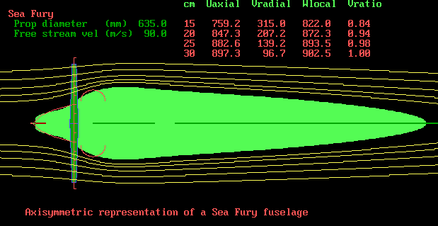
Here is what we get. With a little imagination, the spinner,
radial cowl and rear fuselage are present. Near enough, anyway.

Notice the quantity Vratio. At 15 cm from the axis of
rotation, the axial velocity is only 84% of the airspeed. That
is a serious matter for the design of the prop in that region.
Likewise as we move out toward the prop tip.
So there you have it. The radial distribution of pitch needs
to be adjusted to suit the cowling design. Following this
principle, I designed a prop for the 20cc AT6 class. This prop
was so good, winning 6 Adelaide races in a row, that it has now
been banned in favour of a poorer, weaker, imported prop. Good
for the importers, I guess. C’est la vie.
|